# Launcher
There are 2 types of launchers: 17mm and 34mm.
| Robot | Launcher(s) |
|---|---|
| Standard | 1 x 17 mm |
| Hero | 1 x 17mm, 1 x 42mm |
| Sentry | 2 x 17mm |
| Aerial | 1 x 17mm |
In the 2020 rules, there is an additional 17mm that can be added to any of the ground robots.
# Barrel heat
Firing the launchers generates a "barrel heat" value. Exceeding a threshold results in certain penalties.
# 1. Current heat > heat limit
First person camera view gets blurred
# 2. Current heat > 2(limit)
is deducted, and current heat is reset to .
# 3. Barrel velocity > velocity limit
| Exceed by | HP penalty (of max hp) |
|---|---|
| <5 | 10% |
| <10 | 50% |
| 10 | 100% |
# Analysis
Taking into account the above,
- Minimizing projectile velocity means that we get to fire more projectiles (assuming the same accuracy at lower velocity)
- Launching mechanism must ensure that we do not exceed the velocity limits, because the penalties are extremely harsh (10/50/100% of max hp)
# Sensor
The sensor should give
- tangential (left/right/up/down relative to camera)
- radial (forward/backward relative to camera)
Tangential position will allow for yaw and pitch of the launcher. Radial distance will help calculate the pitch and projectile velocity.
This means a 3D sensor, There are 4 main types of 3D sensors:
| Sensor | Cost | Computational cost | Accuracy |
|---|---|---|---|
| LIDAR | $$$$ | Low | High |
| Stereo cameras | $ | High(*) | Low |
| Time-of-flight cameras | $$ | Low | Moderate |
| Structured light | $ - $$$ | Low | High |
Structured light does not perform well in certain lighting conditions. This is likely to be the case in the competition arena.
Due to budget constraints, stereo is the most feasible solution. To reduce the computational load on the computer, the Intel Realsense D435 has onboard stereo block matching.
# Realsense D435

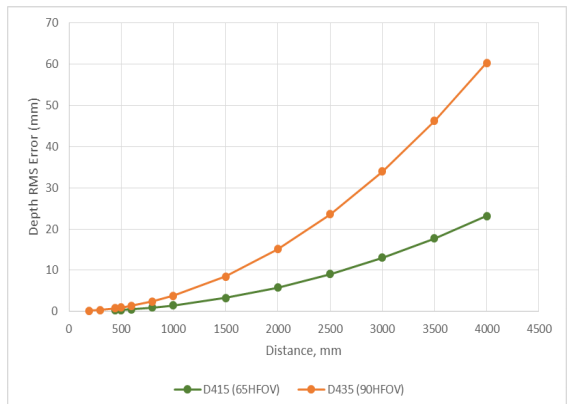
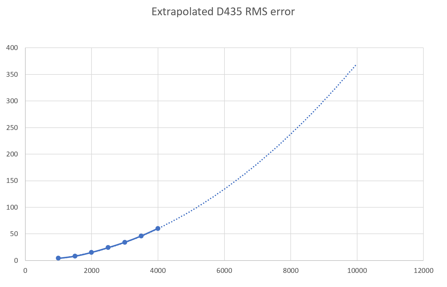
The predicted engagement range should be around 4 - 10m, therefore we need some extrapolated date. By fitting a quadratic curve to the data above:

Between 4 to 10m, there should be an RMS error of 60 - 350mm (6 - 35cm).
To estimate how far we are likely to miss the target by, we will start with a likely lower and upper bounds on time between launcher and target:
To get pitch angle:
| Dist | Time | |
|---|---|---|
| 4m | 1.24 | 133ms |
| 10m | 3.12 | 334ms |
Which shows that at 30 the amount of projectile drop is negligible. This also means that the RMS error of the D435 is unlikely to have any significant impact on aiming performance.
# Motors for ejecting wheels
I propose BLDC motors with field-oriented control (FOC) ESCs (Holybro Kotleta20) running open source firmware (Sapog).
BLDC motors have excellent performance (in terms of torque, torque-to-weight) compared to other types of motors. This will allow us to use smaller, lighter motors on the launcher, reducing the weight of the turret. Which further improves the performance of the pan and tilt mechanism.
Using FOC allows for excellent low RPM torque, which translates to a wheel that rapidly spins up to the desired RPM. It also allows for sensorless RPM by measuring the back EMF of the motors.
Opensource firmware will allow to make any changes or fine-tune the performance as needed. This is not vital, but comes with no additional cost or drawbacks.
# Controller requirements
To start designing the controller, we must first identify the key system requirements.
Compensate for projectile drop
Unlikely (as calculated above). But might still be relavant if there is significant drag.
Compensate for environmental disturbances
Unlikely to be wind in an indoor location.
- Account for launcher dynamics
Important and likely. There will be errors in the pan and tilt mechanism, and in the ejecting wheels. Using feedback control will help us to achieve better performance.
- Aim assist
By using the 3D sensor as feedback, we can ensure that projectiles follow the desired trajectory (in left/right and up/down axis relative to the camera).
- Minimize projectile velocity
By minimizing velocity (and therefore barrel heat), we will be able to get more shots on target. But reducing velocity increases the arc of the projectile and travel time. We will therefore need a controller to compensate for projectile drop and disturbances.
# Model
# Initial velocity target location
Where the solution is given by
Which simplifies to