# Waffle Dudes
# Introduction 🎉
Chen Yao
Hello everyone, my name is Chen Yao, a year two Mechanical Engineering student. With an avid interest in robotics from years of experience with my school robotics team. After participating in various national competitions, I feel that I am rather familiar and comfortable with robotics systems. Nonetheless, I do hope to further build up my knowledge and expertise throughout the course of this project. Additionally, I have a good sense and knowledge in tools handling which I hope to apply to the small-scale robots that we’ll be working with in this competition.
Matthew Ong
Hi, I am a Year 2 Mechanical Eng student. Little experience in robotics - only had a short course with Lego Mindstorm back in secondary school. Main goal of joining this project is to have fun and learn something new at the same time.
Haikal
Hello everyone, my name is Haikal Yusuf, a Year 2 Mechanical Engineering student. I am passionate about anything & everything STEM-related. I have experience with Robotics, having joined the Robotics club in Ngee Ann Secondary School & represented the school in multiple regional & division-level competitions. I mostly worked with the LEGO Mindstorms system but am looking to expand my knowledge to other Robotics Operating System (ROS) while also apply existing ideas to new systems I would get to learn during the span of this competition. I am keen to pursue a minor in Computer Science, even picking up Java in my free time. I hope I would be able to understand & learn better about the software that goes into robotics & hence hope to be able to interact with the Software team & contribute any ideas whilst learning from them too.
Vanessa
Hi, I am Vanessa, a Year 1 Common Engineering student. Previously, I have only read up very briefly about robotics online. As of currently, due to the lack of practical knowledge and experience in robotics, I will read, search and do up some hands-on application so that I will not drag my teammates down. As such, to build up on my knowledge, I will read up more on the operation and pilot side of things to navigate systems better. From there, I can also learn more extensively from my teammates, so that I can craft out my own insights in the ideation of the systems for my teammates. Through this project, not only will I hope to experience the new and interesting robotics environment and learn more of the relevant engineering skills, but also build up friendships and teamwork along the way.
Ashwin
Hi, I am Ashwin Nelanuthala, a year 2 Phd Student in Biological Sciences. I did my B.E in Mechanical Engineering and MSc in Physics. I have worked on a few engineering and science projects which required extensive designing and testing. Some of them include designing fixtures for special purpose machines in industry and high frequency invertors for my master’s thesis. My current Phd also involves designing microscopes and extensive programming for image processing. I would like to help the team in managing both electrical and mechanical systems. While working for this competition, I also wish to improve upon my image processing and software development skills. I hope that my engineering background and experience would help me guide the team to work effectively and I would love to learn and contribute to new ideas and experiences while working on this very interesting project.
# Proposed Manpower Arrangement
| No | Specialisation | Description | Personnel |
|---|---|---|---|
| 1 | Operation | Administrative Tasks | Chen Yao (Leader) |
| 2 | Operation | Accounting, Publicity | Vanessa |
| 3 | Mechanical | Chassis, Suspension | Matthew, Chen Yao |
| 4 | Mechanical | Gun, Gimbal System | Haikal, Chen Yao |
| 5 | Electrical | Battery, Power Distribution System | Ashwin |
| 6 | Electronics | Sensors and Cameras | Ashwin |
| 7 | Software | Onboard Computer and OS | Ashwin |
| 8 | Software | Aimbot/ Aim Assist | Vanessa |
| 9 | Pilot | Operator/ Gameplay Strategy | Vanessa |
# Timeline and Milestones
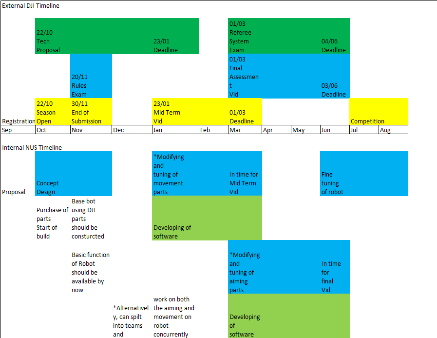
For the external DJI timeline, it is based off past year deadlines.
For the internal NUS timeline, it is a timeline with sufficient buffer zones to satisfy the requirement set by DJI (such as midterm video assessment).
With proper concept design and directions set for the robot, we will move on to acquiring the open sourced DJI robot. After testing its limits and parameters, we will modify and tune it accordingly to suit our competition needs.
# Robot Design Considerations
Having analysed the past year competitions and rule book we have come up with some design considerations for the soldier robot. Of course some of these are based on the previous year's rules so are subject to change.
# Overall Strategy
The general strategy of the soldier robot is to play aggressively. Since the field is mostly flat with some cover, it would suit fast paced, close quarters combat. In the early phase of the game, the soldier robots' main objective is to rush towards the resource island to harass and block the opposing engineer from refilling their hero robot with the 42mm rounds. Ideally, the soldiers would be able to harass the opposing engineer while our own engineer refills the hero robot, massively increasing our damage potential over the enemy's.
Once the hero robot receives the 42mm rounds, the soldier robots will spread out and start to execute quick random attacks to confuse the enemy. The soldier and hero robots can then swarm and pick off stragglers the moment the enemy breaks formation.
In consideration of this playstyle, the soldier robot must be designed to be quick and agile so that it can execute fast attacks and retreat to cover. The robot should be small and light for it to be fast and nimble. A bumper system would be also be beneficial for its aggressive playstyle. Finally, the gun placement should be low so that the robot can go up close and still be able to hit the low lying armour module. This also has the added benefit of lowering the centre of gravity of the robot to make it more stable.
# Robot Type: Soldier Robot
Can only shoot non-aerial robots
- Gun swivel movement does not need to extend to high angles along vertical axis
Only 1 17mm launching mechanism and one laser
- Also limited by "barrel heat" mechanic, hence there is a need to focus on the accuracy of the gun - make every shot count
17 mm ball projectile specifications
Size: about 16.9mm, Weight: 2.9g, Shore Hardness: 90A, Material: TPU
Tests must be done to analyse the firing arcs of these projectiles
Size Constraints
- 600 x 600 x 500 (mm)
# Environmental Conditions
Some slopes up to about 20 degress including a gap on two of the roads where robot has to "jump" across (ability to climb 20 degrees also a competition requirement)
Low centre of gravity while keeping within size constrains to prevent overturns
Suspension to protect the internals and at the same time increase stability of gun
Types of shock absorbers to consider: Hydraulic (from RC car), easily available from hobby stores in Singapore, magnetic dampers which we can DIY from neodymium magnets
# Gameplay Considerations
High mobility required for tight corners and manoeuvres and fast reaction times
- High torque motors for high acceleration
- Mecanum wheels for mobility and agility
# Robot Components
Gun
- Possible mechanisms:
- Compressed air
- Flywheel
- Possible mechanisms:
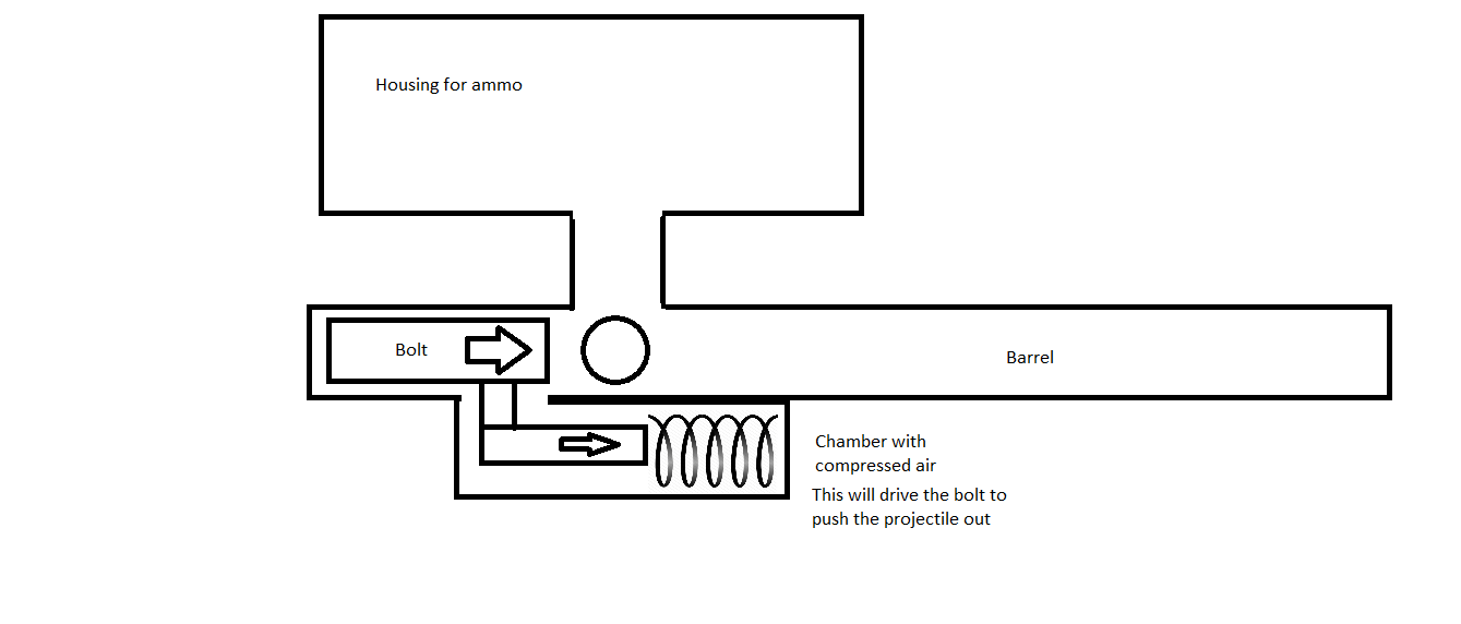
Paintball mechanism using compressed air to be considered for the launcher
Laser for visual assistance when aiming
Compressed air pressure must not exceed 20 MPa, initial firing speed limit of 30 m/s
There is a focus on a aggressive close quarters playstyle with close range shooting. It is important that the gun still needs to be relatively accurate to adapt to newer strategies. Longer barrel length up to 20 cm should be utilised. Should time and resources permit, rifling and Magnus effect due to imparting spin can be considered to increase accuracy.
Ammo collection and feeding mechanism
Ammo box with simple “funnel lid”, the top surface will be lined with soft material like silicone, to prevent balls from bouncing out during refilling
In line with keeping gun placement low, ammo box is placed to the rear of the gun and gravity feed balls into chamber
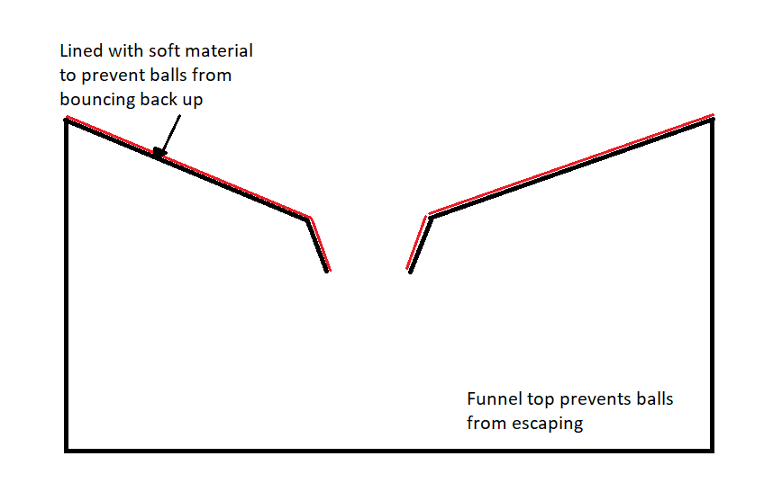
Funnel Design
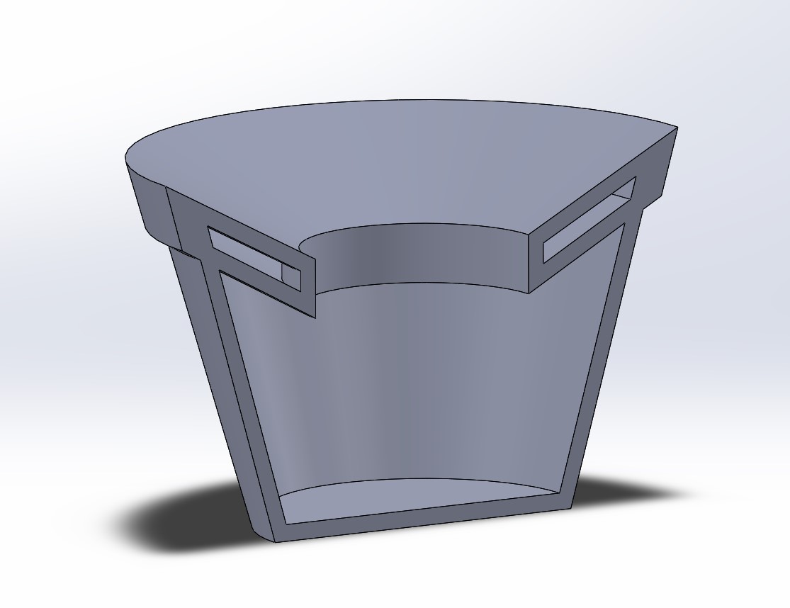
3D Model for funnel
Feeding Mechanism
Base of ammo box will have a rotating disk with a notch for storing one ball at a time. When the notch reaches the outlet, the guide will push only one ball out towards the gun. For a launcher based on a flywheel, fire rate of gun can be controlled by varying the rpm of rotating disk. Software can also be used to control the fire rate in consideration of the “barrel heat” rule. The robot can shoot the first few (e.g. 6) rounds at a faster rate before it reaches the maximum heat. Then it will slow down for the subsequent shots. This will provide the robot will large bursts of damage for an aggressive playstyle.
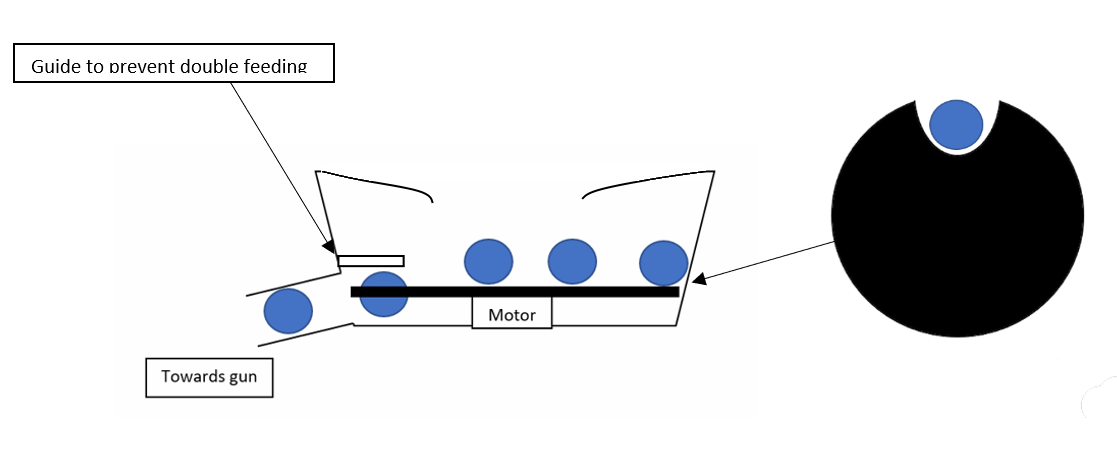
Feeding Mechanism
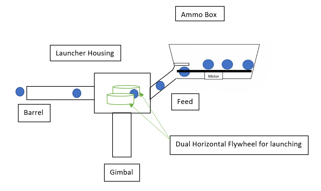
General Overview of Gun using Flywheel Launcher
Gun Stabiliser
Motorised 2- axis Gimbal system
Movement can be done with either servo motors / hydraulics / pneumatic system
Inclined towards servo motors as there is a wide support for it and point of failure is low
Chassis
Aluminium base. Lightweight and sufficiently strong
Can design trusses to support the wheels and suspension
Modify from reference design and manufacture a new chassis as reference design chassis is not able to mount a suspension system
The area of the chassis housing the wheel system have been tapered and narrowed, such that the overall area of the robot is minimized, hence the concept of being small and agile remains. Additionally, this suspension design allows the robot to achieve a lower Centre of Gravity, by making its body wide & flat as the motor & wheels are placed next to the chassis, instead of below the chassis. The shape of the chassis will resemble closely that of a square, effectively shortening the wheelbase (distance between the centers of the front & rear wheels), which allows the robot to achieve a smaller turning radius & thus be very agile & make quick & sharp turns.
Suspension
As there are 20 degrees ramp that the robot has to maneuverer over. A suspension system will be immensely useful in ensuring that the internal structures of the robot is not damaged. In the small-scaled community, various remote-control vehicles use the shock absorber system and thus we have adapted / referenced from them as parts will be widely available and there will be many structures and design to study from. Further calculations will be involved once we received the reference design unit and have the relevant specs to it.
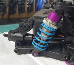
Source: Own
Since there are 4 independent motors, drive shaft can be removed to eliminate points of failure. Instead, the axle area will be mounted with the motor and Mecanum wheel system
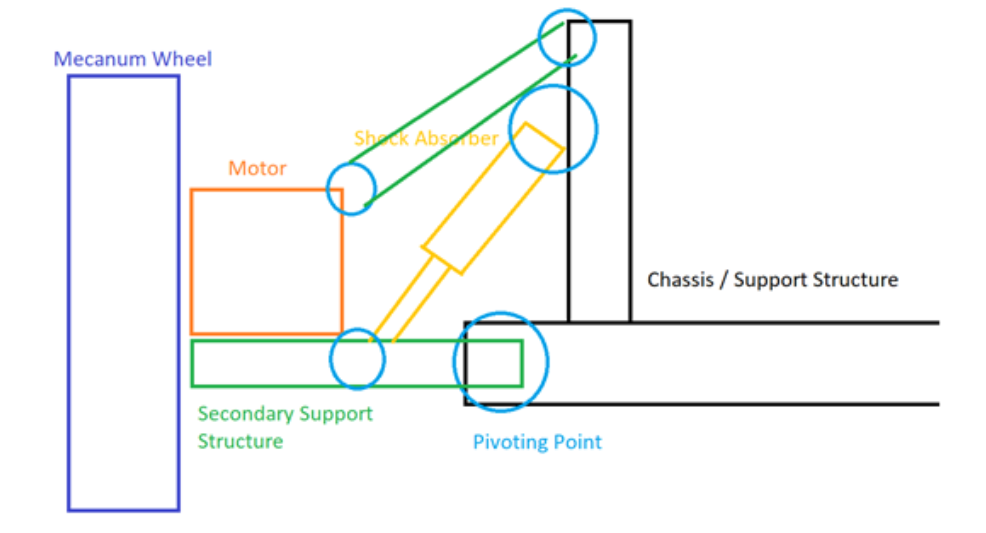
Proposed Suspension design
Bull Bar
It is designed with intentional collision in mind for police vehicles or defensively against large animals in rural roads. AS the bar is rigid, unlike bumper which resist the impact by crumple, it actually causes injuries and death for civilian vehicles.
As such bull bar is banned in the EU. Taking into considering of mitigating damage to the opposing body, we feel that it will be effective in employing it in our robot to ensure that in the event of a collision we will not be damaged and that it will be the enemy that is damaged.
The Bull bar will be inserted on both front and back of the robot to ensure a surround coverage and defensive system.
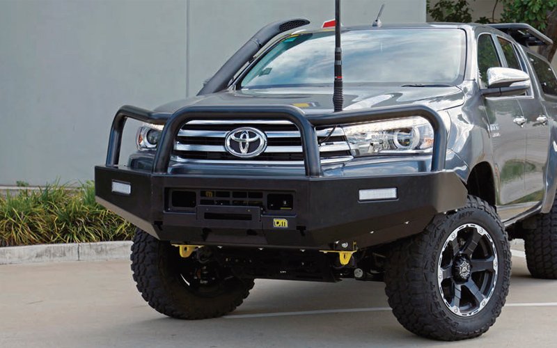 Source: https://www.tjmperth.com.au/product/tjm-tradesman-steel-bull-bar-suit-toyota-hilux-2015-plus/
Can be made inhouse with just a few metal beams
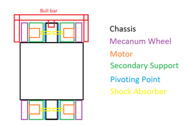
Overview of Chassis
Wheels
- Mecanum wheels for high mobility required for gameplay, including lateral movement
Dual Camera System
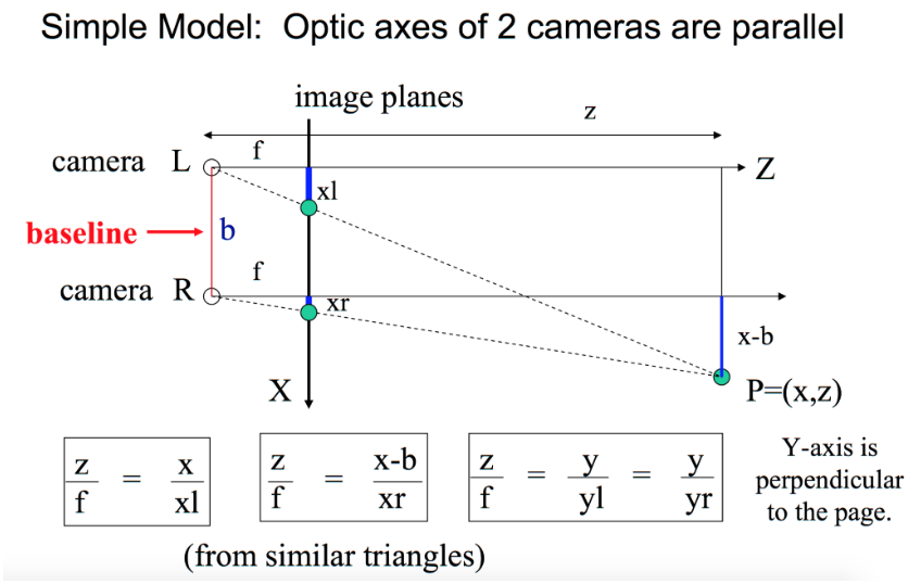
Dual cameras for depth perception using triangulation method
Calculating the distance of the object allows the gun system to compensate for the projectile motion of the bullet by adjusting its angle of elevation
Propose to adapt from exisitng open source projects to design our own
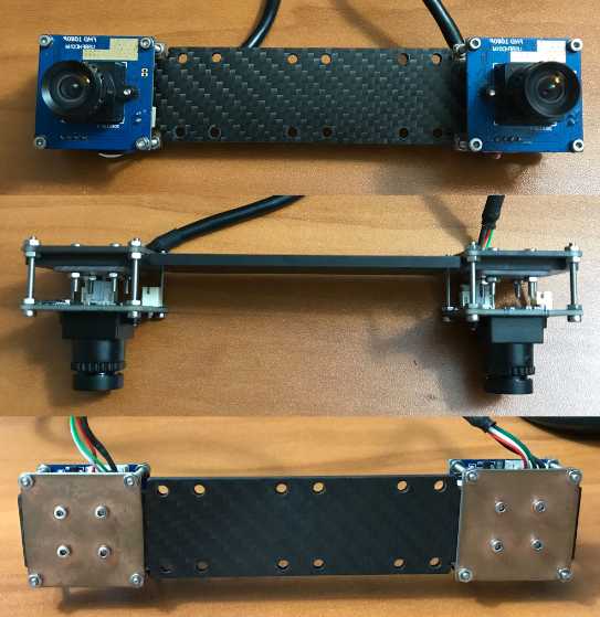
Credit: https://github.com/AlexJinlei/Stereo_Vision_Camera
Baseline The baseline is 120mm, the distance between the 2 camera’s optical axes. A short baseline stereovision system has larger overlapped visual area, which can detect the objects close to the camera. But the disparities at larger distance are too small to be distinguished. A larger baseline system has a larger detection range but cannot detect objects that are close to the camera.
Besides that, the larger baseline system must search the larger range when executing the stereo matching algorithm, requiring more time and hardware resources and the mismatching probability will increase. It is important to choose a proper baseline to meet a specific requirement.
The 12cm baseline system has a working range from 1m to 10m. This working range satisfies & covers the dimensions of the playing area.
This dual camera system utilizes 2 stereo vision cameras & is a low-cost alternative solution to high-end equipment & technology such as LiDAR.
Focal Length
Focal Length = 4.35mm low distortion lens
The focal length is the distance between the lens and the image sensor when the subject is in focus. The short focal length lens has a large view angle but will produce large distortion. The long focal length lens has a narrow view angle, but the distortion is small. The distortion will drastically reduce the accuracy of the depth map. Our Soldier bot needs the large angle view to acquire a big scene of the environment, while at the same time, it requires an accurate depth map to get position information. 4.35mm low distortion lens are suitable.
Supported Frame Format
Time is an important factor in generating the real time 3D map, especially in a varying environment, where objects move & change positions very quickly. Acquiring stereo image pair and calculating depth map will incur some time and hence when the depth map is generated, the moving objects would have changed the position. If the relative velocity of other robots to our robot is around 16m/s, to achieve a 0.5m spatial resolution, the time interval between two frames of image should be 0.3125s (0.5m divided by 16m/s). This corresponding frame rate is 32 frames per second (FPS).
The stereo cameras can accommodate to this & provide an FPS of 38.64 using discrete 800x600 MJPEG format (60 fps), providing a decode time=17ms. This however provides a very narrow field of view.
There is an alternative of using discrete 320x240 YUYV (30 fps) format to provide a FPS of 29.82, with a decode time of 0.8ms. The view angle is equal to 1920x1080.
Theory
If the images of an object are captured from two different points of view, the 3D information can be derived from the disparity of the two images (disparity = difference between xr & xl). Figure 1 is a stereovision system with two parallel cameras. The object point P is projected on the image plane of the two cameras. For left and right cameras, the position of image points of P are different.
xl is the distance between left camera axis and image of P on left camera image plane, and xr is the distance between the optical axis of right camera and image point of P on right camera image plane.
f is the focal length of the two cameras. The distance between two optical axes is called baseline (b). It is notable that the length of xl and xr are different. The equations in boxes are obtained using the concept of similar triangles. From these relations, the location of the 3D points in object space can be derived.
(1) 𝑧 = (𝑓∙𝑏) / (𝑥𝑙 − 𝑥𝑟) = (𝑓∙𝑏) / 𝑑

(2) 𝑥 = 𝑥 𝑙 ∙ (𝑧/𝑓)

(3) 𝑦 = 𝑦 𝑙 ∙ (𝑧/𝑓)
Source: https://github.com/AlexJinlei/Stereo_Vision_Camera
Summary
Hence, considering the tactic of very fast-paced gameplay & the Soldier robots being used to tackle opponent bots head on, we might not require a large field of view since our Operator will use the Soldier robot to focus on a single opponent at a time. The attacking Soldier robots thus may not require the depth map in close quarters since the speed of the bullet is fast enough to compensate for its bullet drop.
This depth perception can be tweaked when applied to other robots that need to stay further back at base & target opponents from a distance & thus, where the depth perception feature would be more important. Here, the depth map will be critical for the auto aim feature of the robots, where bullet drop would be significant & thus, the gun will need to be readjusted with a higher angle of elevation to account to this.
Code necessary for this software is available from an open-source project user AlexJinlei had developed & uploaded to GitHub.
Motor/ Battery/ Electronic Speed Control, Power Distribution Box
Use DJI made parts in the interest of time. Only when unable to meet our requirements (e.g. not enough power), should we consider other alternatives
Must comply to rules, e.g. power consumption to be under 80W
Ultrasonic Sensor
- Improved environment perception
Communication Module
- Produced by DJI as per stated in rule book
On Board Processing Unit
Certain features such as aim assist will be processed in the local computer of the robot for fast and efficient response time and gameplay.
Can consider offloading intensive and non-time critical processing to an external workstation if onboard processing unit is too slow. This will be depend on the onboard processing unit's ability to handle all the tasks and also the bandwidth of communication module
# Additional Quirks and Features
- Pixelized camo / design, high gloss paint, to enhance the difficulty for opponent AI to identify the referee plate on our robot

Source: https://www.whichcar.com.au/car-news/car-camouflage-how-carmakers-hide-prototypes-explained
- Rubber / Spring cushions around the referee plates, thus when the robot is hit, the referee plates not be in the same position for the second shot. Therefore, it lowers the damage taken as the opponent might have to recalibrate their aim
# Fabrication Method
The objective and angle of approach that we are taking is to build a robot as quickly as possible. And fine tune it via trial and error. Thus, we will be adapting solutions that are already available in the market and minimise inhouse manufacturing and development to a minimum. As we feel that the margin of performance gain is insignificant in the grand scheme of things if we do not have a functioning robot at all. Perhaps, we will leave the inhouse development to next year or if we are ahead of schedule for this year’s competition.
Parts from hobbyist level of remote-control vehicles will be preferred. This is because they are readily available off the shelf components from hobby stores. They will provide us with the ease of access, wide range of choices and the support of hobby community.
In the event that parts cannot be found, we will adapt them from exising parts found in live sized vehicles and scale them down accordingly. Small parts can be 3D printed for rapid protopying before the fabrication of the actual part. With access to the school's facilities, strongly believe that we can machine out the necessary and required parts.
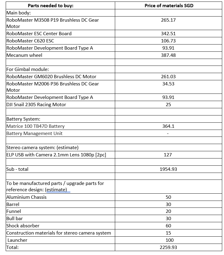
# Budget
