# Team Arigato Roboto
# Introductions
Tay Kai Yang
I am currently a Year 2 Electrical Engineering Student. I have always been excited about how technology has had a profound impact in changing the world. I try to apply whatever EE has taught me wherever possible. I find that I learn best through trial and error, tinkering with stuff till I find the solution. Thus was born my enthusiasm to partake in this competition where the only way to learn is through independent exploration. I believe that the only two possible outcomes of this competition are that either we learn or we win and I strongly believe in the latter.
Prabhakaran Gokul
I am a Year 2 Mechanical Engineering Student. I enjoy hands on work and thus I joined competitions such as Innoventure Programme and Hornet. I got to hone my skills as a mechanical engineer,especially in CAD, through these programmes. I am interested in robotics/AI thus I self learnt computer vision. I also exposed myself to software development by participating in orbital program. I want to pursue my passion in robotics/AI in the future.
Karnati Sai Abhishek
I am a Year 2 Student majoring in Computer Engineering. I am a core believer of the motto that learning does not stop outside the classroom and hence during my time at NUS, I have done self-initiated projects like orbital and also taken part in competitions like Hack & Roll. My immense interest in the real-life application of the concepts I learned in my modules also made me take up a software engineering internship at A*Star during my summer break. My experiences have aided in developing me as a holistic student with both soft and hard skills. Over the past year, I have also grown to like the fascinating field of artificial intelligence and wish to pursue this passion in the future. I believe that the challenging self-learning journey as a Robomasters core team member will aid me in gaining intriguing insights into artificial intelligence.
Hans Kurnia
I am a Year 3 Computer Engineering student. Since my polytechnic days i have participated in several drone involved projects and competitions, such as SAFMC. From these experiences, I have developed an interest in drones as a hobby. Given my interest in drones and remote controlled platforms, I want to take part in the Robomasters competition.
Ijaz Ahmed Navas
I am a Year 2 Electrical Engineering Student. In my first year in NUS I have actively tried to increase my exposure by participating in the Innoventure Programme and Hornet. I have a keen interest in Embedded systems and have accumulated experience in C, Python, Verilog and ARM Development Language. I am excited about the chance to apply the theoretical concepts I have learnt into practice through this experience. If there is one thing I have learnt from the lab sessions and other projects similar to this is that there are always a myriad of factors that you would not have considered in a theoretical model. The smallest issues could snowball and cause an error that would be difficult to trace back. However, when you finally troubleshoot the issue you would have learnt about peripheral issues you would not have ever thought about and the satisfaction is unmatched.
# Proposed Manpower Arrangement
| No | Role | Description | Assigned to |
| 1 | Electronics | Sensor interface; Close-loop Control | Ijaz Ahmed Navas |
| 2 | Software | Computer vision; Motion planning | Abhishek |
| 3 | Software | Linux OS; Sensor drivers | Hans |
| 4 | Mechanical | Gun; Gimbals system | Gokul |
| 5 | Electrical | Power management; Electric Drive; Fail-safe | Kai Yang |
| 6 | Operation | Sponsorships; Chinese-English Translation | Open Position |
| 7 | Operation | Accounting; Publicity Materials | Open Position |
| 8 | Pilot | TX & RX system; Game-play strategy | Open Position |
For people interested to join our team, please contact Kai Yang, Telegram @kaiyang21
# Timeline & Milestones
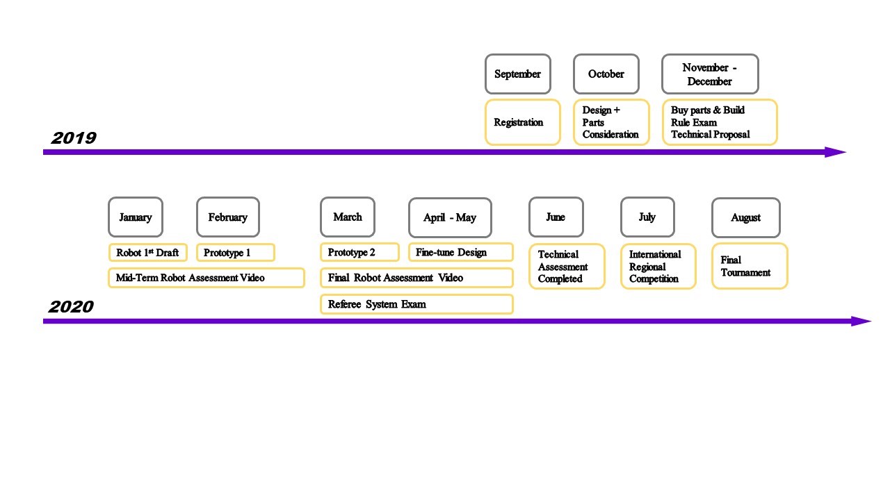
# Robot Design Considerations
Competition Constraints:
- Total Power Supply Capacity: 200 Wh
- Power Supply Voltage: 30 V
- Robot Chassis Power Consumption: 120 W
- Maximum Weight: 25kg
- Maximum Initial Size: 600 x 600 x 500 (mm)
- Maximum Expansion Size: 800 x 700 x 500 (mm)
The job of the standard robot is to complete on field tasks that activate boosts. Therefore, it will be constantly moving through the field and jumping ramps. As such, we agreed that it should be compact, resilient to impact as well as light and agile to navigate the battlefield. Below are the proposed designs to match the role of the standard robot.
Wheels and Suspension:
Wheels: (4x M3508 motor, 4x Robomaster Mecanum Wheels)
- We will be using 4 mecanum wheels for omnidirectional movement.
- Each wheel will have an independent motor and suspension system.
Motors for wheels: (4 x M3508 Brushless DC motors)
- One end of the suspension arm will be hinged to the chassis and the other end will be attached to the wheel. We chose this suspension system as this was a simple design that does the work. Other designs (eg. double wishbone) were more complicated
- We will be using the motor directly to drive the wheels
- A M3508 motor will be mounted on each of the 4 suspension arms, which will then be connected to the wheel. Since the motor is going to be directly driving the wheels, this set up would be apt
- M3508 motor is suitable as it is able to provide a max torque of 1Nm, which is appropriate for the competition. We assumed that the robot is 20kg and also took into account the elevation of the arena(max of 17 degrees)
- A shock absorber with a spring will be fixed to the chassis. The other end of it will be connected to the suspension arm
- We looked at RC cars online for inspiration. We used this to decide on the type of shocks and springs, angle of the suspension to the horizontal(60 degrees)
Suspension Model: (4 x HSP Purple Aluminium 65-87mm Shocks)
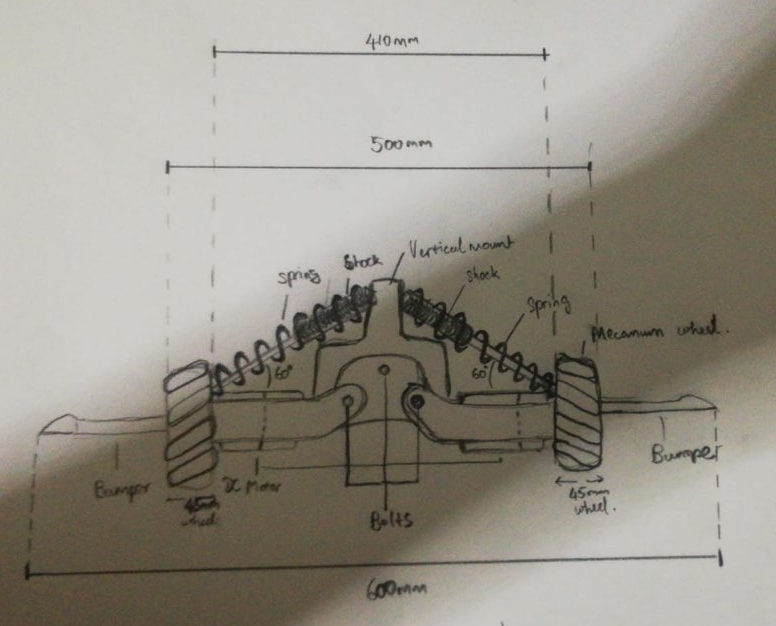
Figure 1a: Wheels and suspension system (front view)
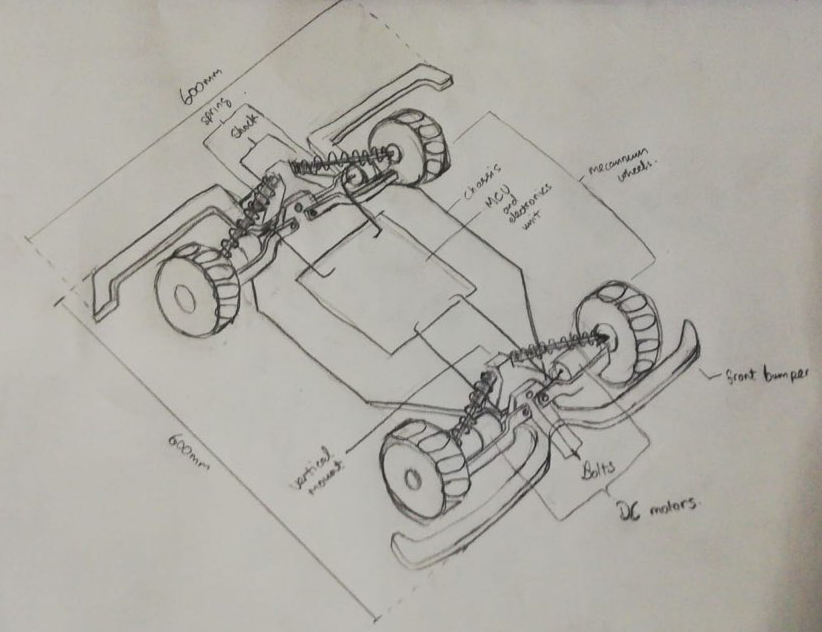
Figure 1b: Wheels and suspension system (isometric view)
Bumper:
- We will have an extended bumper with small wheels at the corners to cover the wheels. This is to prevent the wheels from running up walls, and in the instance of collision with any object at an angle, the small wheels will help to divert the force rather than an abrupt collision. The bumper should be as close to the wheels as possible to prevent obstruction when approaching ramps.
Turret module:
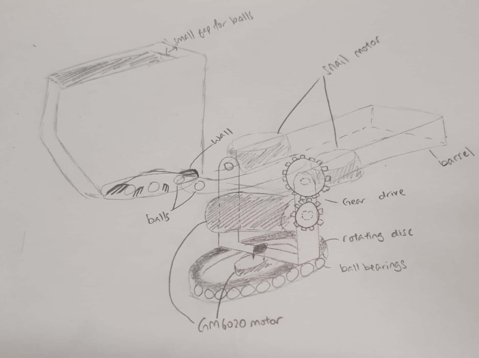
Figure 2: Overall design for the turret module
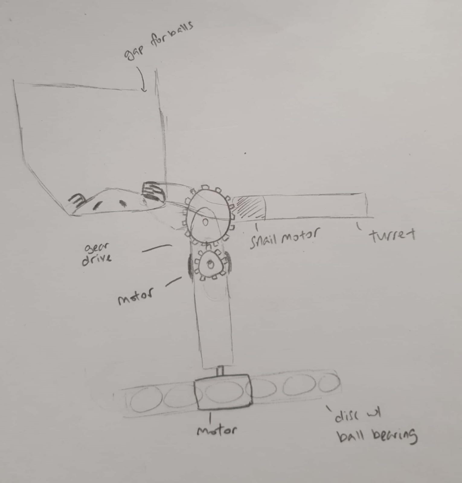
Figure 3: Side view of turret module
Gimbal: (2x RoboMaster GM6020 Brushless DC Motor)
- Two motors are required for the gimbal, one for horizontal rotation and one for vertical rotation of the turret. We have chosen to use the RoboMaster GM6020 brushless DC motor as it has a built-in position sensor that implements position closed-loop control. The accuracy in positioning enables better control for the user. This motor has a built-in driver and does not require an ESC. This motor also returns feedback on real-time motor information such as angle, which enables us to coordinate chassis rotation.
- For horizontal rotation, we will be using a direct drive, with the motor mounted beneath the gimbal. The ‘U’ structure will be rested on a rotating disc with ball bearings so that the weight of the turret module will be resting on the chassis instead of the motor.
- For vertical rotation, we will be using a gear drive. The motor is mounted in the middle of the ‘U’ and connected to a gear outside of the ‘U’ through a gap in the structure. Similarly, the turret is also connected to a gear on the external of the ‘U’. Rotation by the motor drives the pitch of the turret. This design improves stability by helping to even the weight distribution of the turret module as much as possible by placing the motor above the axis of the horizontal rotation.
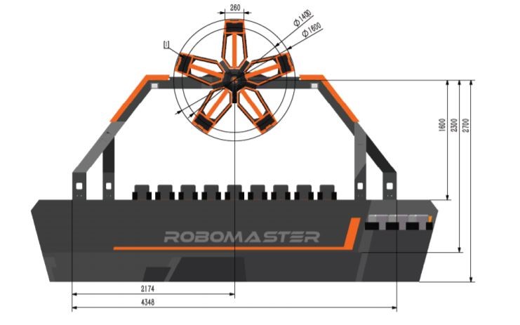
Figure 4: Robomaster 2019 Robotics Competition Power Rune
Source: RoboMaster 2019 Robotics Competition Rules Manual V2.0
- As the standard robot has to achieve field tasks, we consider the cases where it has to hit objects at a height. Based on the power rune set-up obtained from the RoboMaster 2019 competition (Figure 1), the expected height that our projectile should be able to reach is 3.4m. Given a little allowance to account for projectile drop, we target the projectiles to reach a height of 3.5m. Considering a height of 3.5m, we calculated the required angle for our turret at different distances, with the robot at ground level and the turret at a height of 0.4m from the ground.
| Distance from Power Rune (m) | Angle (°) |
| 2 | 57.2 |
| 3 | 45.9 |
| 4 | 37.8 |
| 5 | 31.8 |
We plan to set a maximum tilt angle of 50° as any more will make it difficult for the loading process and the base of the container might hit the chassis. As such, our closest engagement distance for such high objects will be approximately slightly below 3m.
Feeder: (1x RoboMaster M2006 P36 Brushless DC Gear Motor with RoboMaster C610 Brushless DC Motor Speed Controller)
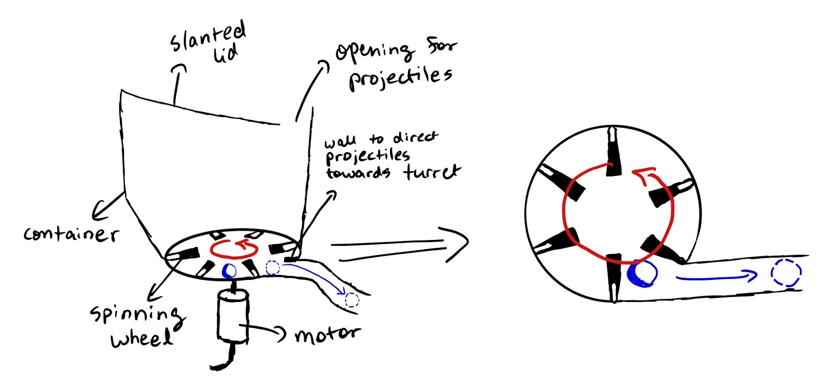
Figure 5: Proposed feeder design
- The feeder system will consist of a container with a slanted bottom mounted on top of the gimbal system to collect the projectiles. We have designed the bottom of the container to be slanted so that the projectiles will be guided towards the feeder.
- The top of the container will feature a slanted curved lid with a gap to allow the projectiles to enter the container. At the same time, since there is only a small opening, projectiles will not get thrown out of the container due to abrupt motions of the robot.
- At the bottom of the container is a rotating feeder with a central peak and slanted sides. When the feeder is in operation, the rotation causes the balls to experience a centrifugal force and roll to the sides, ending up flushed to the walls of the feeder. The fixed protrusions then direct the projectiles towards the opening of the pipe which leads to the turret.
- A curved wall will be erected on one side of the opening so that when the projectiles hit the wall, they will be directed into the pipe. The wall and the protrusions will have complementary gaps to prevent obstruction. The feeder will be controlled using the DC motor. In the case when the pilot wishes to stop firing, he can stop the motor and cut off projectile supply.
- Our feeder has 6 protrusions. The rate at which projectiles are fed into the turret is proportional to the rpm of the motor. For each round spun, ideally 6 projectiles will be fed into the turret. Therefore, for a fire rate of 6 projectiles per second, the motor will only require an rpm of 60rpm. (1 round per second)
- The pipe will have a width of 20 mm, with a small allowance given to ensure that the projectiles do not get stuck in the pipe.
Firing System:(2x DJI Snail 2305 Racing Motor with Snail 430-R Racing ESC)
- We chose to use the RoboMaster Snail Racing Propulsion system as it has a quick response time and high thrust.
- For the firing of projectiles, we will use two motors spinning in opposite directions with a gap of 16 mm to ensure that the projectiles are squeezed in between them and pushed out with utmost power.
Key Considerations for Chassis:
- In order to make sure that the chassis is lightweight and durable, we decided to use carbon fiber for building the main chassis structure
- Since the stability of the robot is essential in making sure that the robot does not topple over during the competition, the weight placement has been designed to be concentrated closer to the base.
- It is important to save on board space and hence to keep the robot compact, we decided to create different compartments for the different modules of the robot. Doing so also aids in making cable management more organized
- The chassis will be designed in a way which ensures that the different modules of the robot like the turret module and the movement module operate independently of each other in order to allow for versatile motion.
Power System:
- System Battery:
- Model: DJI TB47D
- Type: Lipo 6s
- Voltage: 22.2V
- Battery Capacity: 99.9Wh, 4500 mAh (high capacity)
- High-performance battery designed for the Matrice 100 drone platform. Due to this, we would need to mount it to the robomaster battery rack to adapt it to the XT60 interface we need for the robot
- Provides feedback about remaining battery life during operation in real-time.
# Proposed Budget (with parts breakdown)
| Category | Item | Quantity | Purpose/Description | Cost |
| Wheels/
Suspensions | Robomaster Mecanum Wheels | 4 | Two wheels required on the left side and two wheels required on the right side | 176 |
| RoboMaster M3508 P19 Brushless DC Gear Motor | 4 | Required to control and power the Mecanum wheels
Required for suspension system | 316 | |
| HSP Purple Aluminium 65-87mm Shocks | 4 | 69 | ||
| RoboMaster C620 Brushless DC Motor Speed Controller | 4 | 252 | ||
| Turret | RoboMaster GM6020 Brushless Motor | 2 | Required for the gimbal movement in the horizontal and vertical axis | 378 |
| M2006 P36 Brushless DC Gear Motor | 1 | Required for projectile loading in the feeder | 41 | |
| RoboMaster C610 Brushless DC Motor Speed Controller | 1 | 25 | ||
| DJI Snail 2305 Racing Motor | 2 | Required to fire the projectiles | 38 | |
| Snail 430-R Racing ESC | 2 | 16 | ||
| MCU | RoboMaster Development Board Type A | 1 | Main controller to control the different motors, servos | 68 |
| RoboMaster Development Board Cables | 1 | 40 | ||
| Chassis | Estimated budget | 1 | Use of carbon fiber to build the main structure of the chassis | 100 |
| Battery | TB47D Battery | 1 | High-performance 4500mAh battery | 216 |
| RoboMaster Battery Rack (compatible) | 1 | CP.RM.000061
To hold the battery within the robot | 16 | |
| Battery Charger | RoboMaster TB47 Battery 100W Charger AC Cable | 1 | Cable to connect battery to charger | 4 |
| RoboMaster TB47 Battery Charger 100W (without AC cable) | 1 | Battery charger | 19 | |
| Remote Control | RoboMaster Robot Remote Controller Set | 1 | Controlling the actions of the robots using a console | 56 |
| Receiver | RoboMaster Robot Remote Controller Receiver | 1 | Receives commands inputs from the controller | 16 |
| ESC system | RoboMaster ESC Center Board | 1 | Connected to the DC motors. Enables control over the speed of the motors | 5 |
| Total Cost: | $1851 |