The goal of this book is to introduce the reader to the basics of electro-mechanical systems in the context of robotics for the NUS RoboMasters CCA. As such, content specific to the RoboMasters competition will also be covered in later chapters.
This book is meant to accompany workshops hosted by NUS RoboMasters, but content here and be accessed and attempted by anyone!
If you have any feedback on the content presented here or find any mistakes, please reach out Jasshan on:
- Telegram: @jasshank
- Discord: @jasshank
- Email: jasshank@u.nus.edu
How do you use this book?
This book has been written with the intention of being read from front to back. Hence, it makes assumptions about the reader's knowledge in later chapters.
If you already have the required knowledge, just skip straight to the activities portion!
We will be designing an imaginary robot throughout this book, coined "Basic Bot". The bot has the following design goals:
- Move forward, backwards, left and right
- Detect the presence of objects in front of it
- Move based on detected objects
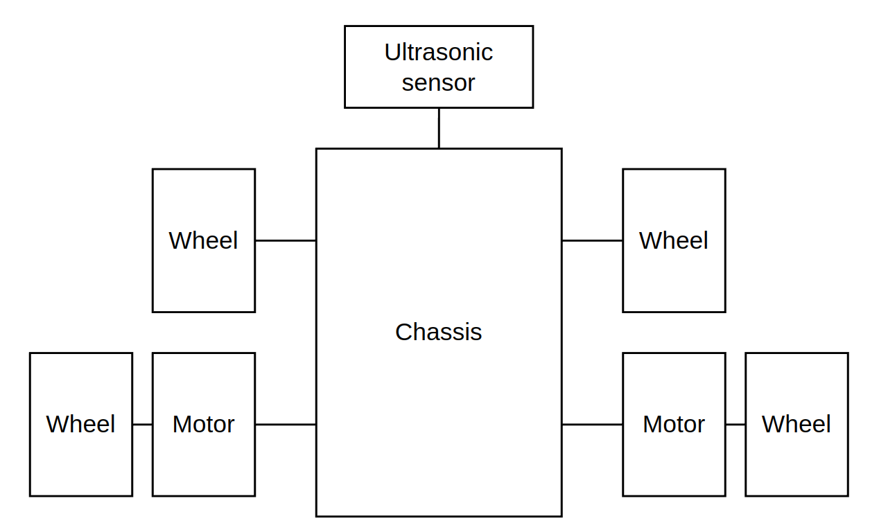
There are many ways we can accomplish this task. In an effort to keep things simple, we will be going through a 4 wheeled robot, with 2 of its wheels driven. It will also have an ultrasonic sensor attached to it's front for presence detection.
Before you proceed to the next section, sketch out or imagine how a robot like this would look like.
The basic basic bot
Taking everything about the description of the bot
There are many ways we can accomplish this task. In an effort to keep things simple, we will be going through a 4 wheeled robot, with 2 of its wheels driven. It will also have an ultrasonic sensor attached to it's front for presence detection.
at face value, we can come up with the following diagram:
However, this isn't the full picture. Motors don't just spin by themselves, and ultrasonic sensors don't just shoot out beams of sound whenever they feel like it. Other devices are needed to interface with these systems!
The more realistic basic bot
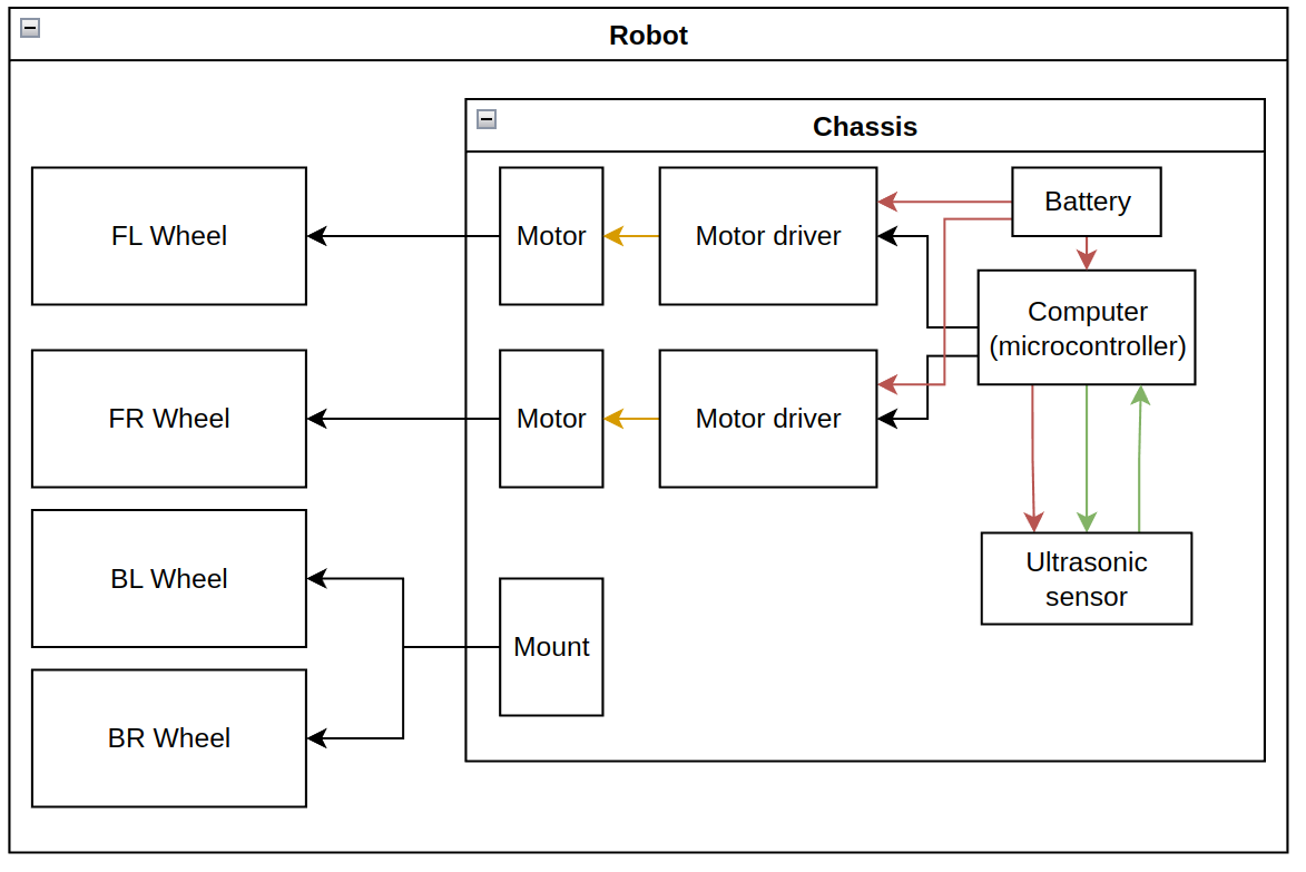
This is a lot of things to look at, so let's break it down:
The motor is connected to a motor driver. As the name suggests, it's entire job is to drive the motor. The motor driver itself is connected to a computer, more specifically a microcontroller.
You can think of a microcontroller as a specialised computer for now. It will be where your code lives and the device through which your code interacts with the outside world.
The ultrasonic sensor is also connected to the microcontroller, which is in-charge of 'taking' and 'receiving' measurements.
Everything also needs to be powered! We will use a battery to do this.
Power and signal
There are 2 main types of connections between devices in the system: power lines and signal lines.
The exception to this rule is the connection between motor and motor driver, which is using a pulsed power line, making it in-between a power and signal line
Power lines, as the name suggests, carries power. Without this connection, none of the electrical component would turn on.
Although it is only 1 wire in the diagram above, it will be 2 in real life: power and ground.
Signals lines are the main way for different parts of the system to communicate with each other. The motor driver takes in signals from the microcontroller so it knows what to output to the motor. The microcontroller also tells the ultrasonic sensor when to send out a sound pulse, and will read the output from the ultrasonic sensor to figure out how long it took for the sound pulse to come back.
Motors go brrr
There's a lot of different types of motors with their own list of features.
When picking a motor, the following questions are usually asked:
- Do I want my motor to spin continuously or move to a specific position?
- How precisely does the motor need to move?
- How strong does my motor need to be (torque)?
- How fast does my motor need to spin (rpm)?
- How big is the motor (physical size)?
These criteria are assuming we are looking for a motor which applies force in the rotational axis. A linear actuator (which is also a motor) would apply force along it's axis
Extracting the first 4 criteria, we can create a rough guideline to pick an appropriate motor:
| Criteria/Motor | Positional Servo | Continuos Servo | Geared DC | Normal DC | Brushless DC | Stepper |
|---|---|---|---|---|---|---|
| Positional? | Yes | No | No | No | Both | Both |
| Precision? | Yes | No | Maybe | No | Yes | Yes |
| High torque? | Yes | No | Yes | Maybe | Maybe | No |
| High RPM? | No | No | No | Maybe | Maybe | No |
If you want to positionally control a continuously rotating motor, you will need some way to keep track of the motors rotation. This can be done using a rotary encoder.
Finally, the type of motor also decides what kind of motor driver you will be using. Smaller servos usually don't require any motor driver, while DC motors, stepper motors and brushless DC motors require their own unique drivers. To understand the type of motor driver required, it is good to understand how these different motors function in the first place! When it comes to this, YouTube and Google are your friend.
Things don't float and matter takes up space
All of the components listed earlier need to be attached to the chassis. Although superglue and duct tape can solve a lot of problems, it's good practice to plan out more permanent mounting solutions when picking your components.
For example, motors usually come with mounting holes; these holes can be used to mount the motor using a L-bracket or a custom mount. Most PCBs(Printed Circuit Board) also come with mounting holes for this purpose.
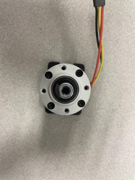
Motor with mounting holes
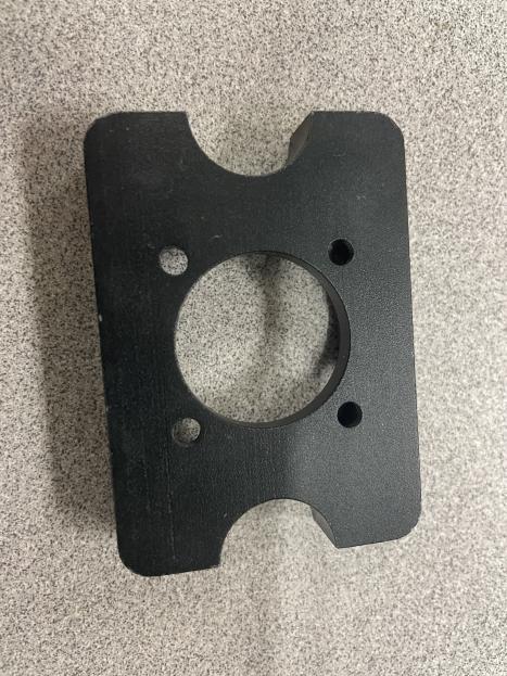
Mounting bracket, front
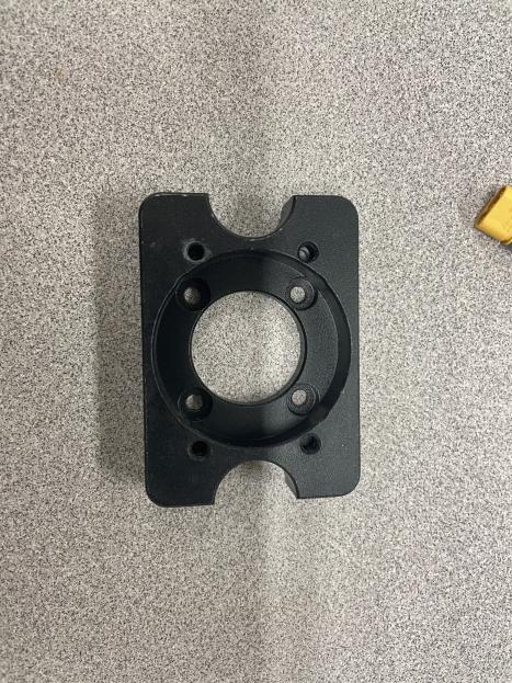
Mounting bracket, back
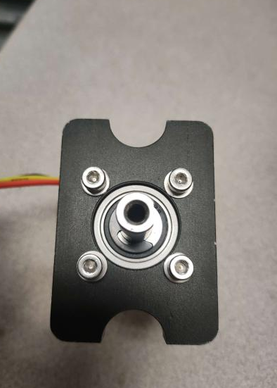
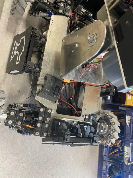
Mounted motor
Although wires might just be lines on your diagram, they WILL take up space in your robot. Care needs to be taken when designing your mounts and chassis to ensure there is enough space to do your wire management.
Software magic
So once you have everything wired up and mounted, there's one last part which is left: the code.
Your code content will be heavily dependent on the type of hardware you're using, but the generic logic flow of your program shouldn't change too much. As such, it's (usually) a good idea to sketch out your ideas for the code; this can be a bunch of arrows and boxes on a piece of paper, pseudo-code, or even a properly drawn out flowchart on a diagramming software.
For the sake of this book, here's an example of the last option for our Basic Bot:
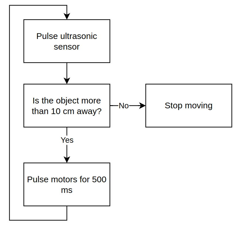
Flow diagrams can also be used to describe error messages along with code flow:
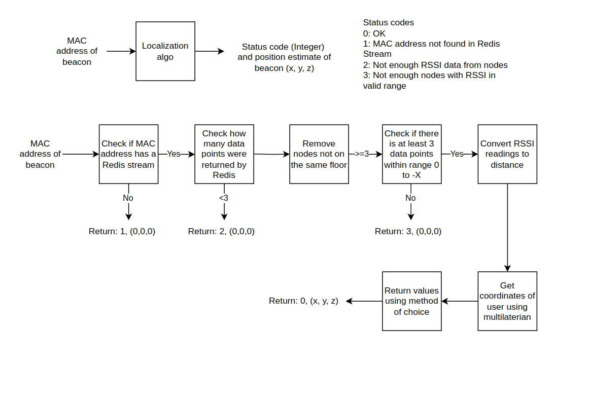
At the end of the day, the goal of any diagram is to communicate with other people (including your future self). There is no reason to make a diagram more verbose than it needs to be, but it shouldn't be so simple it serves no purpose either than to look pretty. First decide who you are communicating to and all other details will fall in place.
Goal
Design a robot vacuum cleaner which is capable of sucking up debris from the floor!
Design contraints
These design goals must be met:
- able to suck up debris from the corners of a room
- know when it is not on the ground
- avoid falling down stairs or ledges
You do not have to consider:
- the charging of the robot
- how it will return to it's charging dock
Deliverables
- Create a diagram to map out all of your robots electrical components.
- Create a separate list to list out the considerations which need to be made for each electrical and mechanical component chosen. For example if a motor is used, how will the motor be mounted?
- Create a flow chart to descirbe how your robot's code will function.
Design your diagrams to act as a reference for yourself in the future. It only has to be as verbose as the content before Activity I. However, you will not be discouraged from making a more detailed diagram from your own knowledge and Google, as long as you are able to answer questions related to your diagram.
It's time for us to flesh out our bot!
As you may have guessed, "power" and "signal" aren't actual terms. To increase the usefullness of our diagrams, we are going to need to add more details to them, such as:
- specific voltages
- communication protocols used
- voltage down (or up) stepping
- battery specification
We will also explore an alternative way to structure our bots program, through a Real-Time Operating System!
System architecture
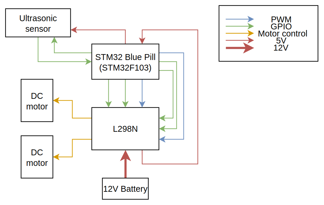
There are 3 major changes in the system architecture:
- Number of motor drivers
- Two different voltage (power) lines
- Two different signal lines
The number of motor drivers were reduced as the motor driver chosen, the L298N, is capable of driving two motors at once, making a second motor driver redundant.
A distinction has only been made between voltage lines, with the battery powering the L298N module, the L298N module powering the MCU and the MCU powering the ultrasonic sensor. This is because the battery will output 12 V, while the MCU requires 5 V.
Power flow:
graph LR;
Battery --12V--> L298N
L298N --5V--> MCU
MCU --5V--> Ultrasonic
The above description is not accurate. The LM7805 linear regulator on the L298N motor driver module steps down the 12V voltage to 5V, which is then connected to the microcontrolller. Certain microcontroller boards also have linear regulators on board, allowing them to accept 12V directly.
The distinction between board and IC (Integrated Circuit) is important as a board can hold multiple chips, including linear regulators.
Finally, the signal lines have been broken down into GPIO(General Purpose Input Output) and PWM(Pulse Width Modulation). The distinction is important as most MCUs have PWM pins limited to a few pins on the board. The extra information provided by this diagram would allow them to build their circuits without having to comb through the datasheets of both the MCU and the L298N module.
GPIO pins in this case refer to pins which have been configured for normal/non-unique input and output tasks.
Choosing a battery
The following steps are general guideline on how to choose a battery in a system (if needed):
- Find the minimum and maximum voltage level.
- Find the maximum current draw and mean current draw.
- Specify how much space is available for the battery.
- Specify the operation time of the system.
- Specify the weight limits of the system.
- Specify if the battery needs to be rechargeable.
From the above points, battery type and specification can be deduced.
Batteries can go boom
The leads of a battery should NEVER be short-circuited together. Depending on the current discharge capabilities of the battery, this could lead to disastarous consequences.
In addition to this, the following rules should also be followed:
- Do not stab batteries.
- Do not drop batteries from high places.
- Do not throw batteries.
- Do not leave batteries unattended while charging (that includes charging overnight!).
- Do not heat up batteries or charge them on a surface where heat can build up (a bed).
- Do not over-discharge batteries past their capacity limit, such as by leaving the battery connected to the system while it continously drains it.
- Do not over-charge batteries while charging, either measure the battery voltage periodically or use a battery charger which automatically stops charging when the desired capacity is reached.
- If batteries show signs of bloating or damage, they should NOT be used. Dispose of them as soon as possible.
- Certain batteries, such as Lithium Polymer batteries, should not be stored while on full-charge as it can damage them.
Although this list tries to be exhaustive, it should be not be used as a rulebook. It is good practice to research how to care and use the battery in your possession safely.
More powerrr
As shown in the example system, the devices in your system can function at varying voltage levels. When designing a system, care should be taken to note down the different voltages present and highlight areas where voltage step-up or step-down is needed.
Stepping voltage up or down
Buck converters can be used to step-down voltage while boost converters can be used to step-up voltage.
Linear regulators can are also capable of stepping-down voltage, but they are more inefficient than buck converters due to how they function. However, they are incredible easy to use due to only having 3 pins: voltage in, ground, and voltage out.
LDO(low-dropout) regulators, a type of linear regulator, has the special function of maintaining the output voltage even when the input voltage is very close to the output voltage. This characteristic of LDOs make it desirable in certain circuits.
Logic level
In the context of digital devices, we refer to the level the device runs as the logic level. For example, the STM32F103 runs at a logic level of 3.3V. However, it is capable of accepting voltages of up to 5V on its voltage input pin.
When connecting the communication (signal) lines of two devices with different logic levels, a logic level shifter might be required. The need for one can be discerned by combing through the datasheets for both devices to find the voltage level where "ON" and "OFF" states are registered. Additionally, certain 3.3 V devices have 5 V tolerant pins, allowing you to at least have one-way communication from the 5 V device to the 3.3 V device without any additional hardware.
Is it all just 1s and 0s?
The goal of a signal line/wire is to allow some form of communication between two devices. There are a multitude of ways to communicate via a single wire, and even more ways when more a single wire is available.
In digital circuits, our communication medium will also be digital. This means that both the sending and the receiving end can only communicate via 2 states, low or high. As such, both sender and receiver needs to be aware of how they are going to be communicating over this line. This is called a communication protocol.
Serial
As you may expected, there are lots of different types of communication protocols, but the most fundament (in my opinion) of all of them is serial communication, also referred to as UART (Universial Asynchronous Receiver-Transmitter).
It consists of 2 wires, excluding ground. It has a receiver and transmit wire, RX and TX for short, and is wired up as shown in the diagram below:
 Image courtesy of embedded.com
A key part of any communication protocol is the data transmission packet; how is the message structured? In human languages, we have grammar rules and punctuation to help us. In communication protocols, the data transmission packet helps in this regard.
 Image courtesy of embedded.com
The data you want to send across will fit in the data frame. The start bit and stop bits are to signal the start and end of the packet, while the parity bit is used for error detection.
Now that we have a way to structure our message, the final piece of the puzzle is still missing; how do we what is a bit? Both devices have no common reference point and have no way of knowing when to start or stop reading for a bit. For example, if I were to send 4 1s in a row, how would the receiving end know it received 4 1s and not a single 1?
This is where the bit rate of the line comes in. If both receiver and transmitter are aware of the bit rate of the line, they know how often to send or check for a bit.
In UART, bit rate is commonly referred to as baud, in symbols per second. In digital communication lines, such as UART, baud = bit rate as the number of symbols in a digital line is 2: 1 and 0. If you want to learn more about UART or are still confused, I highly recommend this video.
Communication protocol terminology
Communication protocol have the following common characteristics:
- Synchronous: Does the protocol use a clock?
- Duplex, Half-Duplex: How many nodes (devices) can transmit information on the same line at the same time?
- Master-Slave or Peer-to-Peer: Does a single device control the communication line, or are all devices equal?
- Differential signalling: Is differential signalling being used?
Understanding what these characteristics mean and how they could be implemented can provide quick insight in to the functionality of the underlying protocol.
Current rating and wire thickness
It is very important to have an estimate of how much current is flowing through a wire in a circuit. Resistance is inversely proportional to cross-sectional area, so a thicker wire will have a lower resistance than a thinner wire. This makes it more suited for carrying higher currents.
The AWG (American Wire Gauge) is one of the methods used to find the the appropriate thickness of wire needed for a given current rating.
Connectors
There are a LOT of different connectors, with different usecases for each of them. Each connector has its own quirks, with some only being used in specific situations.
XT connectors are commonly used for battery connections as it is impossible to plug them in the wrong way around due to being asymmetric and are suitable for high-current applications. There are an example of a wire-to-wire connector.
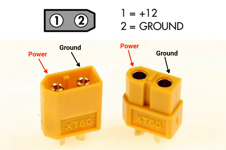 Image courtery of components101.com
When selecting a connector, it is important to consider the following:
- Will the connection be experiencing tension?
- Does the connection require soldering or just crimping?
- Does the connection need to be changed often?
- How much space is available for the wiring?
- Does the connector support the estimated current load?
- Will the connection undergo vibration?
If you're unsure of what connector to use, you can checkout catalogs from brands such as JST, Dupont, Molex or Wago.
while(1)
In a normal microcontroller control flow, nearly all of your logic is placed into a single, infinite loop. In a more complex system however, this can result in a critical piece of code not running till all other components have finished running, which can caused certain functions of the system to become sluggish. Additionally, a badly written component of the code has the capability to slow down all other components.
To circumvent this issue, we can use a RTOS (Real Time Operating System).
What does an RTOS do?
An RTOS is a type of operating system. Personal computers run general purpose operating systems, such as Windows, MacOS or a Linux-based distribution. While general purpose operating systems are designed to run a variety of different software, an RTOS is desgiend with speed and time sensitivity in mind.
Instead of arranging your code into a single/super loop, we can break them down into multiple tasks. Each task will have it's own infinite loop. A priority should then be assigned to each task. Using this information, the RTOS will run all the tasks concurrently with the different levels of priority affecting their running time.
Concurrent != Parallel. Concurrency involves running multiple tasks on a single processing core, switching between tasks rapidly to give the illusion they are running at the same time. Running tasks in parallel involves running them across multiple cores, resulting in them truly running at the same time.
Just like general purpose operating systems, there are different implementations of RTOSs, such as FreeRTOS, Zephyr and NuttX. If you would like to know more about a specific implementation or just want to learn more about the other features of RTOSs, do checkout the individual documentations of the above implementations.
Goal
Design a 1 Degree of Freedom (DOF) gimbal capable of holding a 500 g weight. The gimbal needs to be controlled by two buttons, rotating it clockwise and anti-clockwise.
Design constraints
The gimbal should prevent the weight from rotating along the y-axis, where the x-axis is into the screen, y-axis is along the screen and the z-axis is upwards. In order words, the gimbal will prevent pitch rotation.
Deliverables
- Create a system architecure for this design, complete with labelled power and signal lines.
- Reasoning on how your design works in 2-3 sentences.
- Relative thickness of wires used for each power and signal group (from thickest to thinness).
RoboMasters University Championship
In RMUC, teams develop 7 different types of robots with various functions to face off on the battlefield. Each team's participants will control their robots to attack the enemy's robots and Base by launching projectiles. At the end of the match, the team with the highest remaining Base HP wins.
RoboMasters University League
RMUL consists of 2 events - 3V3 and the 1v1 Standard Confrontation.
In the 3V3 Match, teams develop their own Standard, Hero, and an autonomous Sentry Robot and pilot their robots to launch projectiles against opponent robots and bases. The winner of the match is the team with the higher remaining Base HP. Participating teams can advance to the RoboMaster University Championship (RMUC) through the Scoring and Ranking System.
In the 1V1 Standard Match, teams independently develop their own Standard Robot and pilot their robots to launch projectiles at each other. The winner at the end of the Match shall be the team with the higher remaining Standard Robot HP.
Rules, rules, rules
To participate in the RoboMasters competition, team's are required to build a fleet of robot with the constraints set out in the rules manuals.
There are 3 different manuals:
- Rules Manual
- Robot Building Specifications Manual
- Participant Manual
Both RMUC and RMUL have their own Rules and Participant manuals, but share the same Robot Building Specification. All the manuals can be found online (or in NUS RM's Discord!). Before designing a full robot, engineers should AT LEAST read the rules manual pages relevant to the robot you are designing, as well as the specification manual.
Although most of the rules manual is not directly related to robots, it is very important as it will outline the importance of the different features on the robot as well as its overall role in the entire competition.
Understand the rules well, and all other design goals will fall in place.
Goal
Explain how the light indicator module will be installed on a robot chassis.
Design constraints
- As set out in the specification manual. (Read the rules!)
- Build off a mecanum-wheeled robot with a 360 degree firing mechanism on a gimbal.
Deliverables
Sketch of your design with the location of the light indicator module.
The sketch should have:
- all relevant dimensions to understand where the lightbar will be mounted
- any assumptions made about the underlying design